
Why ICS?
RF repeaters are very economical and convenient solution for coverage extension of mobile services, since they do not require any cable or optical link between the donor station and the service area. However, if the isolation between the donor antenna and the service antenna is not sufficient, the feedback from the output to the input of the repeater can cause self-oscillation, destroying the service of the whole cell of the wireless network.
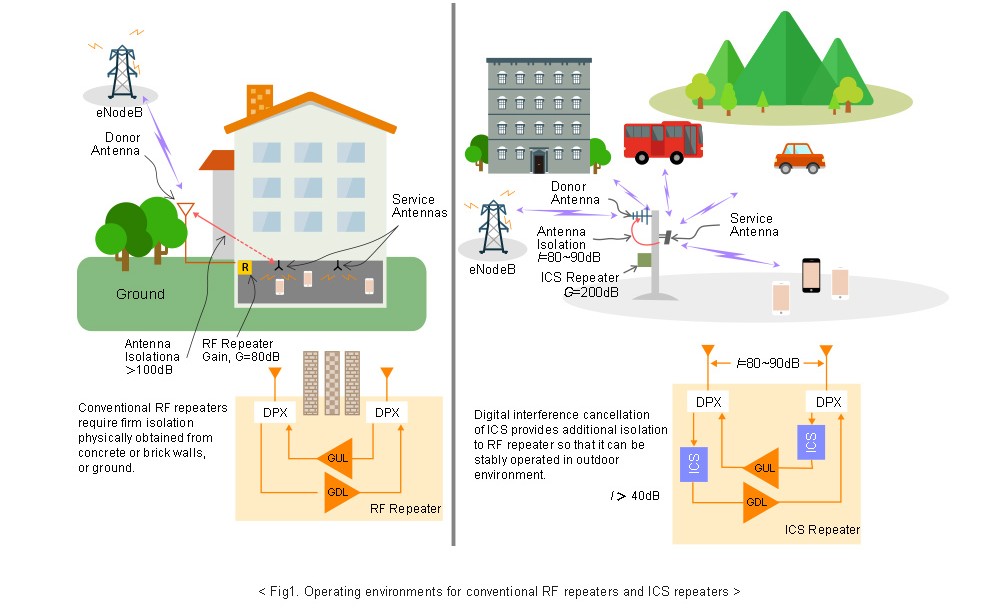
Therefore, conventional RF repeaters usually require antenna isolation at a minimum of 15dB~20dB higher than the repeater gain, so that the feedback does not make an oscillation. This limits typical applications of RF repeaters to indoor coverage where donor antenna and service antenna are separated with enough isolation physically obtained from concrete or brick walls, or the ground.
ICS (Interference Cancellation System) has been devised to overcome such a limitation. It can create an effect of more than 40dB isolation by cancelling the feedback interference input to the repeater. Thanks to this additional isolation, donor antenna and service antenna need not be separated by wall or ground. They can be installed at the same pole with just a few meters of distance, or they both can even be attached to the same body of the repeater being operated with a lot higher gain than RF repeaters. This feature enables ICS repeaters to be used outside the building with enough gain up to 100dB, thereby maintaining the convenience and economic benefits of the RF repeaters. Also it can be employed to antenna-embedded repeaters to improve indoor coverage without installing a separate donor antenna outside the building or house. Fig.1 illustrates the operating environments for RF repeaters and ICS repeaters.
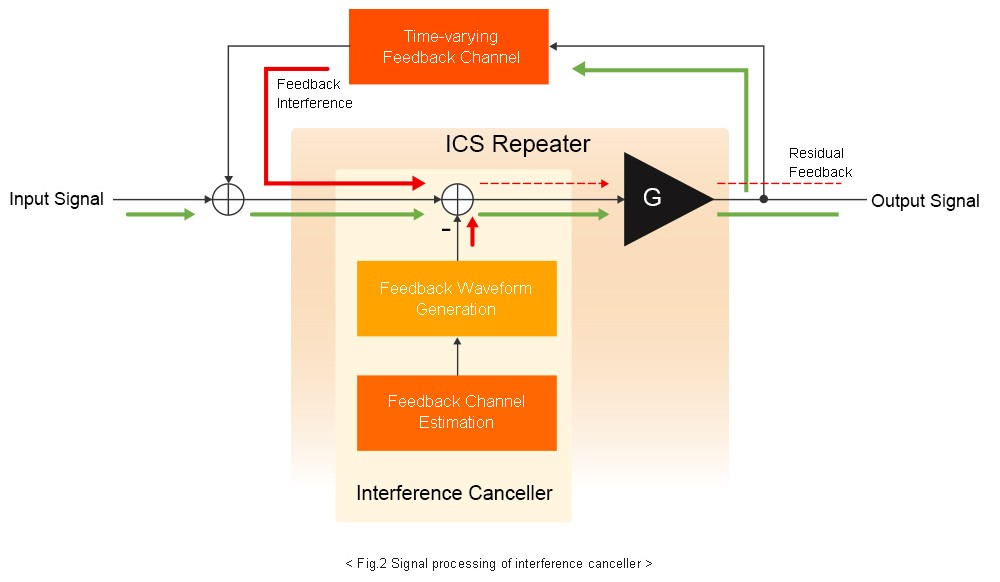
Signal processing for ICS is comprised of feedback channel estimation, feedback waveform generation and subtraction functions as shown in Fig.2. Among these the feedback channel estimation is the most important factor in the performance of ICS. It is crucial to accurately estimate and continuously track the time-varying feedback channel in real time. Then, by using the transmit signal and estimated feedback channel, the feedback waveform is generated and subtracted from the received waveform which is the sum of the signal from the donor station or user terminals and the feedback from the repeater output.
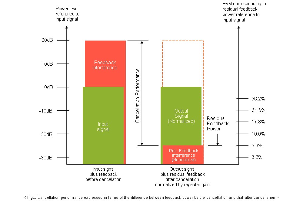
An important measure of cancellation performance is the maximum ratio of feedback power to the signal power for which ICS can work, keeping the ratio of the residual feedback power to the signal power less than an acceptable level after cancellation. The acceptable level of the ratio is usually given in EVM, which depends on the air standard. For example, WCDMA requires EVM to be less than or equal to 12.5%, and LTE requires EVM to be less than or equal to 8% in general.
In many cases, this performance measure is expressed as an inequality of the repeater gain and antenna isolation, G ≤ I + Cmax (dB), where G is the repeater gain, I is the isolation between donor antenna and service antenna, and Cmax is the maximum ratio of feedback power to the input signal power in dB.
Another measure of cancellation performance is the difference between the input feedback power before cancellation, and residual feedback power after cancellation measured in dB as shown in Fig.3. This can be obtained from the EVM (Error Vector Magnitude) of the repeater output and the ratio of feedback power to signal power at the repeater input. Since EVM is the percentage ratio of the error magnitude to the signal (symbol) magnitude, taking 20log(EVM/100) gives the ratio of residual feedback power to the output signal power in dB under the assumption that residual feedback interference is uncorrelated, and noise and other interference powers are negligible. Thus, it can be easily measured in a laboratory environment where the feedback power and the signal power can be accurately controlled.
Since ICS should adapt to the time-varying feedback channel, the immunity to Doppler fading in the feedback channel is very important - especially when it is installed by a roadside or near a railroad. That is, cancellation performance should maintain the service quality, against channel variation due to the moving vehicles. In many ICS implementations, some factors of cancellation performance for static channels and those for Doppler-fading channels conflict with each other. In other words, if the performance for static channel is maximized then the performance for Doppler-fading channel is degraded and vice versa. Therefore it is necessary to maintain a good trade-off and optimization between the performances for the two types of channel characteristics.
For Rayleigh Doppler-fading in feedback channel, the peak level of feedback is near to more than 10dB above the average feedback power. Thus, the ICS should have at least 10dB margin of cancellation performance at the operating gain. Otherwise the ICS should automatically reduce the repeater gain so that it can safely work without oscillation while enduring the service coverage reduction.
Moving vehicles generate Doppler fading in not only the feedback channel but also the input signal, especially for the uplink side. It results in magnitude fluctuation in both the input signal as well as the feedback. Therefore the ICS repeater should be equipped to properly handle such a wide dynamic range by using an accurate automatic gain control function.